
Content Information
On this page...
- General
- Stopping Sight Distance
- Stopping Sight Distance Adjustment for Grade
- Stopping Sight Distance for Trucks
- Decision Sight Distance
- Intersection Sight Distance
- Horizontal Intersection Sight Distance
- Passing Sight Distance
- Measuring Sight Distance
- Vertical Profile
- Example Problem 6D-1_1: Determining Stopping Sight Distance on Grade
- Example Problem 6D-1_2: Intersection with a Two-lane Highway
- Example Problem 6D-1_3: Intersection with a Four-lane Expressway
- Example Problem 6D-1_4: Signalized Ramp Terminal Connection
- Chronology of Changes
General
A driver needs adequate sight distance along a roadway to make safe and efficient decisions. Several types of sight distance are discussed in this section:
- Stopping sight distance – The distance traveled in the time it takes a driver to recognize an object ahead, decide to stop, and then stop their vehicle.
- Decision sight distance – The distance traveled in the time it takes a driver to recognize an object ahead, decide whether to stop their vehicle or change their path, and then make the maneuver.
- Intersection sight distance – The time gap acceptance distance needed for a driver to enter an intersection.
- Passing sight distance – On two lane roadways, passing sight distance contributes to the determination of No Passing Zones.
\({\Large Quick\ Tips:}\)
- Stopping sight distance should be provided throughout the entire length of the roadway.
- For sag vertical curves, a design exception is required for curves that meet passenger comfort criteria, but do not have a fixed lighting source.
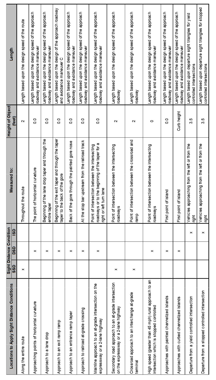
- Refer to Table 8 for guidance on which type of sight distance applies and the boundaries.
Back to top
Stopping Sight Distance
Stopping sight distance (SSD) is the length of roadway ahead that is visible to the driver. This distance allows a driver to see an object in the roadway and stop their vehicle before colliding with the object. A roadway should be designed to provide continuous stopping sight distance throughout the route.
\({\Large Attention:}\) A formal design exception is required wherever stopping sight distance cannot be provided.
SSD consists of two components:
Brake reaction distance – The distance a vehicle travels from the moment a driver spots the object until the driver applies the brakes.
Braking distance – The distance a vehicle travels from the moment the brakes are applied until the vehicle comes to a stop.
Combining these yields the following equation:
\[\mathrm{SSD} = 1.47\,Vt + 1.075\,\frac{V^2}{a} \qquad \text{(Equation 6D-1_1)}\]
where:
SSD = stopping sight distance, ft
t = break reaction time, 2.5 s
V = design speed, mph
a= deceleration rate, 11.2 \(ft/s^2\)
(Reference: Equation 3-2 AASHTO Greenbook, 2011)
Table 1 provides minimum SSD derived from Equation 6D-1_1, although greater lengths are desirable.
Stopping Sight Distance Adjustment for Grade
Vertical grades greater than 3% affect the braking distance component of stopping sight distance. On upgrades, braking distance decreases. On downgrades, braking distance increases. Most roadways are traversed in both directions; therefore, a vertical grade for one direction of travel increases the needed stopping sight distance, while decreasing the needed stopping sight distance for the other direction of travel. In most cases the available sight distance on downgrades is greater, so adjustments to the sight distance values shown in Table 1 are not normally needed for downgrades. Exceptions are one-way roadways and roadways with independent vertical alignments.
The following equation can be used to determine the needed SSD on downgrades:
\[d_B = \frac{V^2}{30\left[\left(\frac{a}{32.2}\right) - G\right]} \qquad \text{(Equation 6D-1_2)}\]where:
\(d_B\)= braking distance on grade, ft
V = design speed, mph
a = deceleration, 11.2 \(ft/s^2\)
G= grade, \(rise/run\), \(ft/ft\)
(Reference: Equation 3-3 AASHTO Greenbook, 2011)
This is added to the distance traveled during brake reaction time (1.47Vt) to determine stopping sight distance.
Example Problem 6D-1_1, Determining Stopping Sight Distance on Grade
Back to topStopping Sight Distance for Trucks
Trucks are heavier than passenger cars; therefore, they need a longer distance to stop. The values shown in Table 1 do not consider the physical characteristics of trucks, such as weight. However, adjustment factors for trucks are not necessary. Drivers in trucks are able to see farther down the road because the driver is at a higher elevation above the roadway surface, thus increasing the available sight distance. The increase in the height of the driver offsets the need for additional braking distance resulting from the truck’s weight.
Back to topDecision Sight Distance
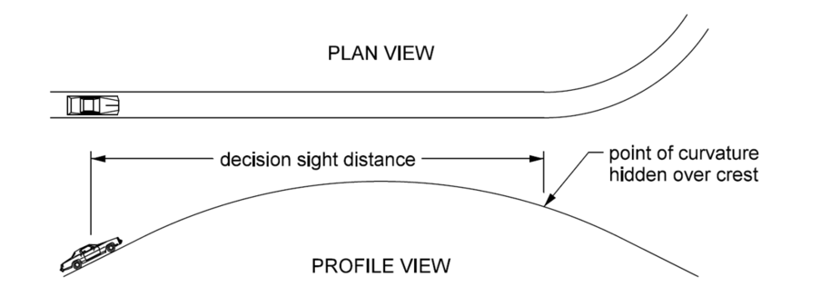
Decision sight distance (DSD) provides drivers approaching changes in the roadway environment, such as intersections, interchanges, or areas where the roadway turns as shown in Figure 1, time to recognize the change and decide to either change their vehicle path, reduce their speed, or stop their vehicle.
Low Speed Environments
Providing stopping sight distance on roadways in a low-speed environment is usually sufficient. Roadways in low-speed environments are usually affected by visual noise from competing sources such as roadway elements, traffic, traffic control devices, and advertising signs. This visual noise makes it difficult for drivers to perceive a hazard and decide to change their path. As a result, most drivers will stop. In addition, the alignment and roadway cross-section are restricted in urban areas due to constraints in the roadside, which makes providing decision sight distance difficult.
High Speed Environments
Providing decision sight distance in high-speed environments is desirable. More freedom exists to adjust the alignment or cross-section in a high-speed environment. If the alignment or cross-section cannot be adjusted, the decision point should be relocated, for example moving an exit gore that is hidden over a crest vertical curve to a point upstream of the high point.
The AASHTO Greenbook provides decision sight distance based upon design speed and various avoidance maneuvers for rural and urban roadways. The Department prefers to use avoidance maneuver C (speed/path/or direction change on rural roads) for high-speed environments, including urban interstates and freeways. Refer to Table 2 for decision sight distance values.
DSD=1.4Vt (Equation 6D-1_3)
where:
DSD = decision sight distance, ft
t = break reaction time, t varies from 10.2 to 11.2 seconds
V = design speed, mph
(Reference: Equation 3-5 AASHTO Greenbook, 2011)
Table 2: Decision Sight Distance, Avoidance Maneuver C.
Intersection Sight Distance
Since vehicle paths cross within intersections, the potential exists for various types of crashes. To reduce potential crashes, an area within the roadside, clear of obstructions, should be provided so drivers at an intersection can see drivers on the intersecting road approaching the intersection. This area is referred to as the clear area. Objects that restrict intersection sight distance should be removed, lowered, or relocated outside of the clear area. Intersections can also be relocated away from the sight obstruction.
To determine whether an object is a sight obstruction, the designer needs to consider both the horizontal and vertical alignments of the intersecting roads, as well as the elevation of the object. To do this, the designer needs to construct departure sight triangles and then determine the elevations of the object(s), the driver at the intersection, and the driver approaching the intersection.
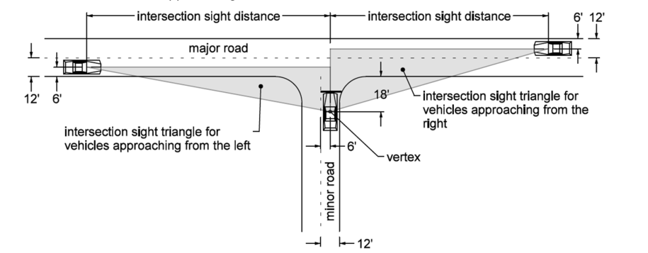
Departure sight triangles for vehicles approaching from the left or right, like those shown in Figure 2, should be provided for stop sign controlled intersections and signalized intersections where right turns on red are permitted. The area within the triangle (the clear area) needs to be free of obstructions that restrict the view of vehicles approaching the intersection.
Horizontal Intersection Sight Distance
The vertex, or decision point, is where a stopped driver at an intersection is located. The designer should assume the vertex is in the middle of the approach lane. The vertex is measured 18 feet from the edge of the major road traveled way. This distance can be reduced to 14.5 feet but should only be used in locations where it has been deemed necessary to avoid removing protected obstructions such as historic buildings, or in areas where an existing sideroad intersection is close to bridge.
Intersection sight distance along the major road is determined by the following formula:
\[L = 1.47\,V_{\text{major}}\,t \qquad \text{(Equation 6D-1_4)}\]where:
L = sight distance along major road, ft
\(V_{\mathrm{major}}\)= design speed of major roadway, mph
\(t_g\)= time gap, s
(Reference: Equation 9-1 AASHTO Greenbook, 2011)
The distance is measured down the middle of the approach lane on the major road.
The time gap variable (tg) represents the time a stopped driver will accept to accelerate and complete a turning maneuver into traffic. The acceptable time gap is different for a right, left, or crossing maneuver. The acceptable time gap also depends on the design vehicle making the maneuver. Table 3 contains minimum gap acceptance times for maneuvers and design vehicles based upon standard conditions: little to no skew, the major road is a two lane roadway, and the approach grade on the minor roadway less than +3.0%.
Table 3: Time Gap.
*0.5 seconds added to AASHTO Greenbook values for older drivers
Refer to Table 4 for additional time needed for non-standard conditions.
Table 4: Adjusted Time Gap.
Expressways in a rural environment usually have wide depressed medians. Most medians are not wide enough to store a combination truck and allow sufficient clearance to the through lanes. Therefore, the major roadway’s horizontal and vertical alignment should provide sufficient intersection sight distance for combination trucks to make a left turn or crossing maneuver without having to stop within the median. Additionally, the provided sight distance should allow a driver in a truck to see approaching drivers in passenger cars.
Providing intersection sight distance for trucks on divided roadways with wide medians can be difficult in areas with rolling terrain. When intersection sight distance cannot be achieved for trucks, the greatest possible length should be provided, but not less than:
- intersection sight distance needed for a single unit design vehicle to depart from the median, or
- decision sight distance to the intersection.
Vertical Intersection Sight Distance
Sight triangles determine the clear area needed. For an object located in the clear area, the designer needs to determine the elevations of the driver’s eye at the intersection and the approaching driver’s eye to determine if the object affects sight distance. The height of eye of a driver in a passenger car is 3.5 feet above the roadway surface. The height of eye of a driver in a truck is 7.6 feet above the roadway surface. With this information, the designer can determine if an object will obscure sight distance. Vertical profiles that do not allow a stopped driver at an intersection to see an approaching driver’s eye should be flattened to provide intersection sight distance.
Example Problem 6D-1_2, Intersection with a Two-lane Highway
Example Problem 6D-1_3, Intersection with Four-lane Expressway
Example Problem 6D-1_4, Signalized Ramp Terminal Intersection
Back to topPassing Sight Distance
No Passing Zones locations are determined using Section 7A-1 of the Traffic and Safety Manual.
Back to topMeasuring Sight Distance
Sight distance along a roadway can be limited by the horizontal or vertical alignment, as well as physical features such as longitudinal barriers, back slopes in cut sections, and bridge berms.
Horizontal Alignment
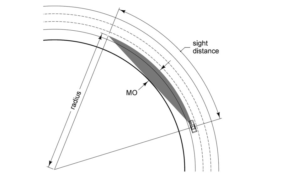
Physical features along the inside of curve can restrict sight distance. The following equation can be used to determine if the physical feature limits sight distance. The middle ordinate (MO) is the perpendicular distance from the vehicle path along a curve to the face of the physical feature. See Figure 3 for a graphical representation.
\[\mathrm{MO} = R\left(1 - \cos\left(\frac{28.65 \times S}{R}\right)\right)\]where:
MO = middle ordinate, ft
R = radius of the vehicle path, ft
S = stopping sight distance, ft
If a feature limits sight distance, the designer can adjust the horizontal alignment or modify the roadway’s cross-section to provide adequate sight distance.
Vertical Profile
A change between tangent grades results in a crest or sag vertical curve. The high point (turning point) of a crest vertical curve can limit sight distance to an object in the road or a change in the roadway alignment. Sight distance on sag vertical curves is usually limited by the headlight sight distance of a vehicle.
Crest Vertical Curves
Rate of vertical curvature (denoted by the variable K) is used as a design control on crest vertical curves to ensure the crest vertical provides stopping sight distance for a selected design speed.
\[K = \frac{L}{A} \qquad \text{(Equation 6D-1_6)}\]where:
K = rate of vertical curvature
L = length of vertical curve, ft
A = algebraic difference in grades, %
The Department uses a minimum vertical curve length of 3 times the design speed and Equation 3-41 from the AASHTO Greenbook to determine minimum rate of curvature. Combining the Equation 6D-1_6 and Equation 3-41 from the AASHTO Greenbook results in the following equation:
\[K = \frac{S^2}{100\left(\sqrt{2h_1} + \sqrt{2h_2}\right)^2} \qquad \text{(Equation 6D-1_7)}\]where:
K = rate of vertical curvature
L = length of vertical curve, ft
S = stopping sight distance, ft
\(h_1\) = height of driver’s eye, ft
\(h_2\) = height of object in road, ft
The height of the driver’s eye (h1) in a passenger car is 3.5 feet and the height of the object in the road (h2) is 2.0 feet, refer to Figure 4. See Table 5 for minimum K values for crest vertical curve design.
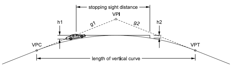
Table 5: Design controls for crest vertical curves.
Decision Sight Distance
In the measure of decision sight distance, AASHTO specifies the 2.0 feet object height criterion adopted from stopping sight distance. The Department suggests using the height of the pavement surface (0.0 feet) when measuring decision sight, since the decision point may be a point of curvature in the roadway’s alignment, a lane drop or a lane add, an exit or entrance ramp taper, a turn lane taper, or an intersection. If decision sight distance to the pavement surface cannot be achieved, the designer needs to adjust the geometry of the roadway or relocate the decision point where the adequate decision sight.
\({\Large Attention:}\)
Special attention to pavement surface drainage should be given to crest vertical curves on roadways where K is greater than 167. K values in excess of 167 can result in flat areas that are slow to shed water.
Sag Vertical Curves
Like crest vertical curves, rate of vertical curvature (K) is used as a design control for sag vertical curves. The Department uses a vertical curve length of 3 times the design speed and Equation 3-48 from the AASHTO Greenbook to determine a minimum rate of vertical curvature. Combining Equation 6D-1_6 and Equation 3-48 from the AASHTO Greenbook results in the following equation:
\[K = \frac{S^2}{400 + 3.5S} \qquad \text{(Equation 6D-1_8)}\]
where:
K = rate vertical curvature
S = sight distance, ft
Table 6: Design controls for sag vertical curves.
\({\Large Attention:}\)
Special attention to pavement surface drainage should be given to sag vertical curves on roadways where K is greater than 167. K values in excess of 167 can result in flat areas that are slow to shed water.
If a roadway has continuous lighting, the length of a sag vertical curve (L) may be based upon passenger comfort instead of headlight sight distance.
The following equation may be used to determine the minimum length of a sag vertical based upon passenger comfort:
\[L = \frac{AV^2}{46.5} \qquad \text{(Equation 6D-1\9)}\]where:
L = length of sag vertical curve, ft
V = design speed, mph
A = algebraic difference in grades, %
(Reference: Equation 3-51 AASHTO Greenbook, 2011)
Table 7: Design controls for sag vertical curves based upon driver comfort.
\({\Large Attention:}\)
For sag vertical curves, a design exception is required for curves that meet passenger comfort criteria, but do not have a fixed lighting source.
Table 8: Sight Distance Application and Boundaries.
Back to top
Example Problem 6D-1_1: Determining Stopping Sight Distance on Grade
Determine the required stopping sight distance on grade for the following situation.
The roadway consists of the following:
2-lane state highway
Design speed = 60 mph
6% down grade
Solution:
1. Use Equation 6D-1_2 to determine the required braking distance:
\[d_B=\frac{60^2}{30\left[\left(\frac{11.2}{32.2}\right)-0.06\right]} =416.92\ \text{ft}\]
2. Add this to the distance traveled during brake reaction time (1.47Vt) to determine the required stopping sight distance:
\[\mathrm{SSD}_{\mathrm{req}} = 1.47 \times 60 \times 2.5 + 416.92 \approx 640\ \text{ft}\]Back to top
Example Problem 6D-1_2: Intersection with a Two-lane Highway
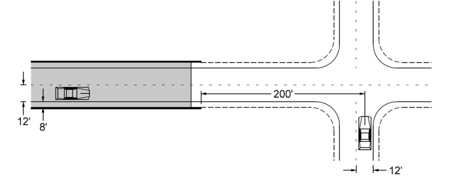
Determine if the bridge barrier rail restricts intersection sight distance for a left turn maneuver.
Given:
Local Road intersecting a 2-lane state highway
Design speed of the 2-lane highway = 60 mph
Bridge barrier height = 34 inches
Design vehicle – passenger car
Solution:
Using a time gap acceptance value from Table 3 and Equation 6D-1_4, determine the required intersection sight distance:
L = 1.47×60×8.0 = 705.6 ft ≈ 710 ft
- Construct departure sight triangle:
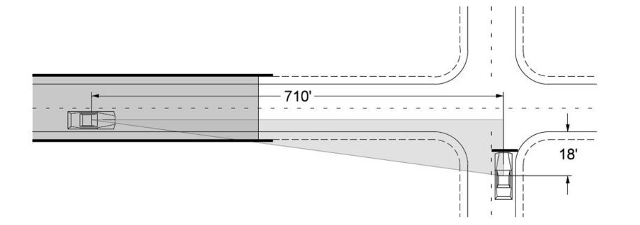
The barrier rail falls within the sight triangle.
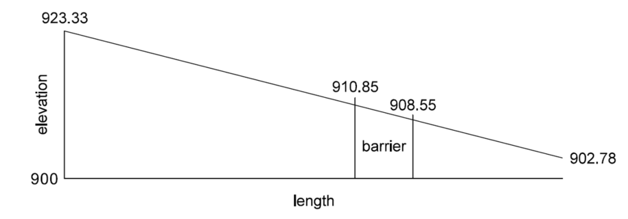
Calculate the elevations of the drivers and obstruction:
Elevation of the driver on the local road (minor road):
Elevation of the driver on the two-lane highway (major road):
\[\mathrm{Elev}_{h_2} = 919.83 + 3.5 = 923.33\ \text{ft}\]Elevation of the top of barrier varies from 910.85 to 908.55 feet.
\({\Large Note:}\)
Pavement surface elevations can be determined from survey .tin files, design files, or construction plans.
The height of the barrier is a sight obstruction.
Calculate the available intersection sight distance:
Since the barrier is the sight obstruction, the available intersection sight distance can be determined from similar triangles.
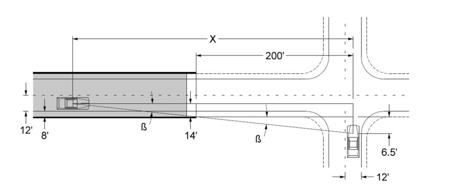
Discussion:
When determining available intersection sight distance, the designer should use minimum values from Table 3 and assume the stopped driver is 14.5 feet from the edge of the through roadway.
Possible solutions are:
- Reduce the design speed of the state highway to 55 mph.
- Widen the bridge.
- Relocated the local road away from the bridge.
Back to top
Example Problem 6D-1_3: Intersection with a Four-lane Expressway
Calculate the required intersection sight distance need for a truck to turn left from a minor road approach to a rural expressway.
Given:
Local road intersecting a 4-lane rural expressway
Design speed of the expressway = 70 mph
Median width = 64 feet
Design vehicle = Combination truck
Assume the vehicle will turn into the outside lane
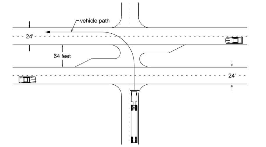
Solution:
- Sight triangle to the left:
Using the time gap acceptance value for combination trucks from Table 3 and Equation 6D-1_4, determine the required intersection sight distance:
L = 1.47×70×10.5 = 1080.5 ft ≈ 1085 ft
Sight triangle to the right:
Calculate the time gap acceptance value required for the combination truck to cross near lanes, median, and far lane.
To cross the near lanes, add 0.7 seconds for the additional 12’ lane
To cross the median:
Covert the median width to equivalent 12’ lanes:
To cross the far lane, add 0.7 seconds.
Gap acceptance time = 11.5 + 0.7 + 3.7 + 0.7 = 16.6 seconds
Using the calculated gap acceptance time and Equation 6D-1_4, determine the required intersection sight distance:
L = 1.47×70×16.66 = 1708.1 ft ≈ 1710 ft
Construct departure sight triangles:
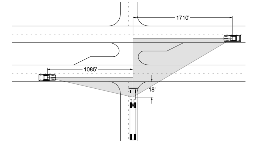
Vertical alignments:
The elevations of the driver in the truck and the drivers in the passenger cars need to be derived from the profiles. If the designer determines that the driver’s cannot see one another, the profiles need to be adjusted to provide the recommend sight distances calculated.
Discussion:
In some instances, intersection sight distance for a combination truck to complete a left turn or crossing maneuver without stopping in the median can be difficult to provide. For these instances, it is desirable to provide intersection sight distance for a single-unit truck stopped within the median should be provided.
Sight triangle to the right for a single-unit truck:
Using the time gap acceptance value for a single-unit truck from Table 3 and Equation 6D-1_4, determine the required intersection sight distance:
L = 1.47×70×9.5 = 977.6 ft ≈ 980 ft
Construct departure sight triangle:
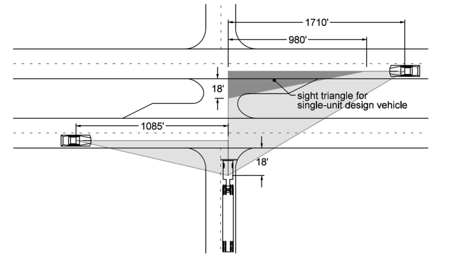
Back to top
Example Problem 6D-1_4: Signalized Ramp Terminal Connection
Determine if the separation barrier and chain link fence restricts intersection sight distance for a right turn maneuver.
Given:
Ramp intersecting a 4-lane urban roadway
Design speed of the 4-lane roadway = 40 mph
Separation barrier height = 2 feet 10 inches
Design vehicle – passenger car
Signalized intersection
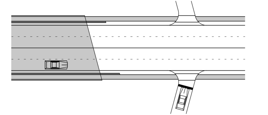
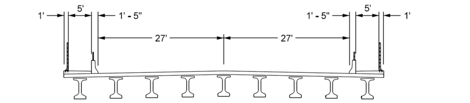
Solution:
- Using a time gap acceptance value from Table 3 and Equation 6D-1_4, determine the required intersection sight distance:
L = 1.47×40×7.0 = 411.6 ft ≈ 415 ft
Construct departure sight triangle:
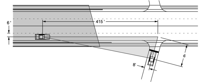
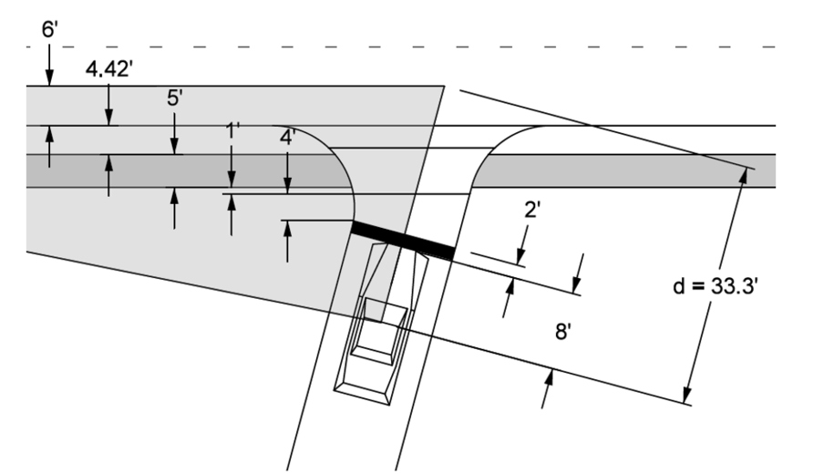
As shown in Figure 3, the barrier rail and chain link fence fall within the sight triangle.
Move the vertex to 18 feet from the edge of the through roadway (i.e. the driver moves forward to improve sight distance):
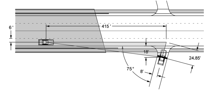
Dimension d in this case can be determined by:
Calculate the elevations of the drivers and potential obstructions:
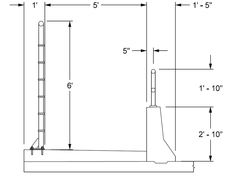
Elevation of the driver on the local road (minor road):
Elevation of the driver on the two-lane highway (major road):
\[\mathrm{Elev}_{h_2} = 687.18 + 3.5 = 690.68\ \text{ft}\]Elevation of the top of barrier rail varies from 686.34 to 685.69 feet.
Elevation of the top of pedestrian hand rail varies from 688.17 to 687.52 feet
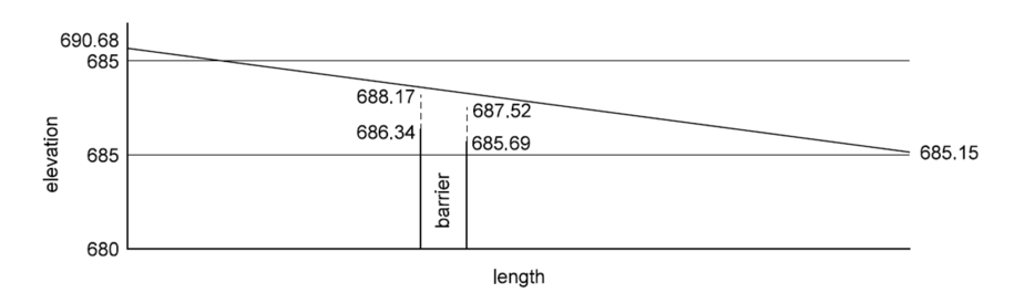
The height of the barrier rail and pedestrian hand rail is not a sight obstruction.
Discussion
If the barrier rail were a sight obstruction, the barrier rail could be moved to the outside of the bridge where the chain link fence is shown in Figure 6, or a sign restricting right turns during a red phase could be added.
If the pedestrian rail were a sight obstruction, the pedestrian rail could be removed.
Back to top