
Content Information
On this page...
Plan sets can be very large; therefore, plan sheets are organized in a specific manner. This organization places related information together so it is not scattered throughout the plans, for example: typical cross sections are contained in the B sheets; estimated quantities are contained in the C sheets; mainline plan and profile information is contained in the D sheets; side road plan and profile information is contained in the E sheets; detour plan and profile information is contained in the F sheets; and so on. Organizing plans in this manner helps with the plan development process. In addition, it allows both designers and contractors to quickly locate information. Plan organization also assists in the printing process. Some sheets are printed in color, and others are not. Grouping sheets together reduces the number of files sent to the color printer. It also helps to standardize which types of sheets are printed in color.
Back to topPlan Organization
Plan sheets should be numbered as follows:
Plan Sheet Basics
Information contained varies from sheet to sheet; however, the following information is to be on the bottom of every plan sheet:
Design Team.
County(s).
Project Number.
Sheet Number.
Current date stamp, directory, and file name.
When developing plan sheets, keep the following in mind:
- Every sheet needs to be covered by an engineer’s signature.
- To the extent possible, avoid repeating information within the plan. Say it once and say it right. This reduces the possibility of conflicts within a plan.
- Check information to determine if it over-rides, duplicates, or conflicts with other contract documents. Eliminate duplication where possible and resolve conflicts. Investigate the impact over-riding one contract document will have on other contract documents. A hierarchy of documents is listed in Section 1105 of the Specifications.
- Place information so it is easy for the contractor and inspector to find. Special notes shown on plan or profile views should be referenced from the C sheets, usually in a tabulation or Estimate Reference Note.
- Provide sufficient information so that the contractor can construct the project, but don’t overwhelm the contractor with information. In essence, do not include information just because you can – include information that will be of value to the contractor.
- Special notes and drawings should only be used for unique situations and used only when they are absolutely necessary. Just because you can change something doesn’t mean you should.
- If a color standard road plan needs to be modified, include it in the U sheets as a black and white sheet per Section 21E-4. This excludes any modified TC Series Standard Road Plans as outlined in Section 1F-10.
- If adding labels, use the naming conventions from the specifications.
- Something that is clear to you is not necessarily clear to the contractor. Similarly, something that is confusing to you may not be confusing to the contractor.
- Each bid item requires an associated specification, standard, detail, or plan note.
Sheet and Text Scales
The designer must select an appropriate plan scale for the project and type of sheet. For most rural projects, the plan and profile sheets will be 100 scale. However, 50 scale may be used in rural areas where the complexity of the project requires greater detail. For urban projects, the designer may choose between 20 scale and 50 scale depending on the level of detail necessary. Geometric, Staking, and Jointing Sheets sheets are typically 20 scale. Sidewalk sheets are typically 10 scale. For information on cross section sheet scales, refer to Section 1F-23a.
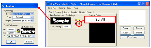
When using Plan View Labeler and Profile Labeler, it is important to set the text attributes appropriately with respect to the sheet scale that has been selected. Table 1, below, shows the relationship between sheet scale and text parameters. Figure 1 shows an example of text parameters for a 100 scale sheet. After setting the desired text parameters, set the symbology for the shape and leader tabs to match the parameters tab by selecting Set All Parameters as shown in Figure 1.
Plan Quality Checklist
- Is Design Team information correct and at the bottom of each sheet?
- Is the County(s) included at the bottom of each sheet?
- Is the project number correct and at the bottom of each sheet?
- Are sheet numbers at the bottom of each page? Are sheets numbered sequentially in black text?
- Are the current date stamp, directory, and file name at the bottom of each sheet?
- Is information located on appropriate sheets?
- Are sheets legible?
- Have plan sheets prepared by other offices been appropriately incorporated into the plan set?
- Is color use appropriate according to Section 21E-4?
- For a D4 Submittal, have the following items been included:
- Road Design Engineer’s seal on the first Road Design Sheet
- Sheet block for bridge projects with design and file numbers on all sheets