
Content Information
On this page...
B sheets provide typical grading and paving cross sections for a project. Typical cross sections are a graphical representation of existing conditions or work to be preformed within the station limits of a roadway. A typical cross section represents the predominant section of roadway and shows the major elements.
This section only pertains to roadway typical cross sections for new construction.
Back to topGeneral
Typical cross section sheets should not contain alignment geometrics or superelevation information. That information is to be shown on the plan sheets.
Major items normally shown on a typical cross section include: ditches, shoulders, pavement surfaces, and median width (dimensioned vertically and horizontally); foreslopes and backslopes (labeled with the slope); and subdrains, barriers, and curbs (identified by type).
Horizontal roadway dimensions on typical cross sections should be expressed in feet and should be referenced to the alignment or base line. Horizontal dimensions should be shown to the nearest half foot increment. If a horizontal dimension is to the nearest foot, then show the dimension as a whole number. (Example: a 12 foot lane is shown as 12’ not 12.0’)
Vertical roadway dimensions on the typical cross section should be expressed in inches and shown to the nearest half inch for existing conditions, as well as new construction. The vertical scale is usually shown exaggerated to clarify the thickness of the various layers.
The cross slope of an item should be identified by percent with an arrow showing the downward slope direction, or when applicable, shown as matching the existing slope. Side slopes are to be identified as a horizontal to vertical ratio.
The profile grade location should clearly be shown on the grading and paving typical cross sections.
The standard typicals and components in the Road Design Details show the most common case for each roadway type. If modification of typical cross sections is necessary, refer to Section 3D-3 for further guidance.
Back to topTabulations
Some typical cross sections are shown in the direction of travel. The tabulation should be filled out in the direction of station. In no case should the designer attempt to the mirror the typical components to the direction of stationing.
View a sample below.
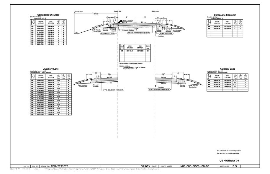
The designer should avoid station overlap when using multiple cross section components for a roadway.
Tabulations with the direction of travel should reference the prevailing route direction and not the compass direction. (Example: Interstate 29 is a north/south route. Sections of I-29 in Sioux City have a compass direction of east/west. The direction of travel for the typical cross section should be north/south.)
If a dimension varies, show the minimum and maximum values. Other information within the plan should show why the dimension varies. (Example: The plan set should show where a taper or transition curve begins and ends along with the associated geometrics.)
\({\Large Attention:}\)
NOTE: The designer should never show a dimension as “varies”.
Back to top
Layout
The designer should select design criteria for roadways within the project limits from Section 1C-1. Knowing the design criteria is essential to developing typical cross sections. The designer should also be aware of how the project will be let. Selecting typical cross sections for a grading job is different than developing typical cross sections for a grade and pave job. The designer should also ask for a preliminary pavement determination before developing typical cross sections.
Back to topGrading Typical Cross Sections
The grading typical cross sections should be the first typical sections shown in the plan set. The grading typical for the major roadway should be shown first, with minor roadways following in sequential order as they are encountered in relation to the major roadway.
Grading typical sections should be shown or tabulated in the following sequential order:
- Major roadway
- Minor roadway 1
- Minor roadway 2
- Minor roadway…n
- Interchange (Ramps) 1
- Interchange (Ramps) 2
- Interchange (Ramps)…n
- Access way/Entrance 1
- Access way/Entrance 2
- Access way/Entrance…n
- Detour 1
- Detour 2
- Detour…n
If a project contains two major roadways of equal importance, the roadway with the highest classification should be shown first. (Example: Interstate 35 typical cross sections would appear in the plan set before Interstate 235 typical cross sections.) If work is proposed on two roadways with equal classification on the same project, the roadway with the higher traffic volume should be shown first.
Back to topBackbones
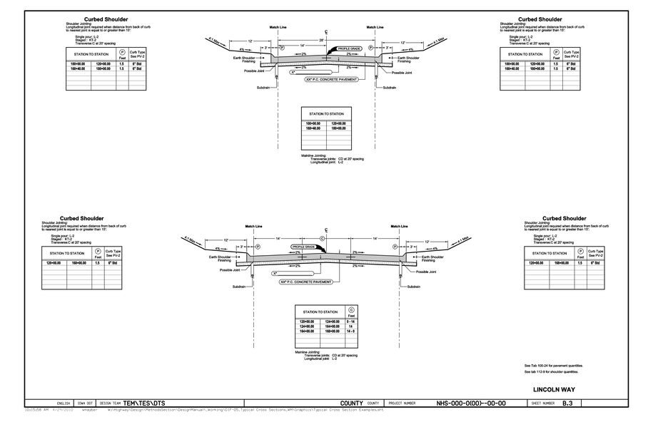
The backbone section represents a basic roadway section. A backbone section shows the type of pavement and width of the roadway. Roadways with more than one backbone should be shown on the same sheet. (Example: A two lane roadway may widen out within the terminals of an interchange. One backbone section is needed to show the two lane roadway and another is needed to show the three lane roadway.)
View a sample below.
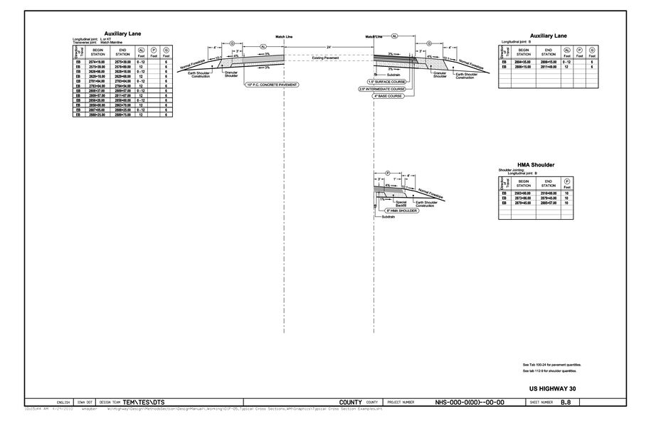
Backbone sections for existing roadways are available for shouldering or widening projects. The designer will need to use the edit text tool to annotate the existing pavement width.
View a sample below.
Paving Typical Cross Sections
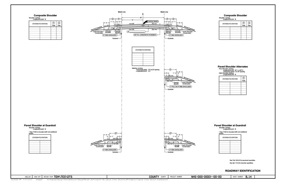
Paving typical cross sections should be shown in the same order as the grading typical sections. The designer should select a backbone section which represents the pavement type and number of basic lanes for the roadway they are developing. The designer should then select the various shoulder types encountered within the project limits. As a project is developed from D2 to plan turn-in, the number of shoulder types usually increases. The shoulder type which is predominant should be shown with the back bone section with other shoulder types shown in the order they are encountered. If the number of shoulder types creates a need for more than one sheet, the designer should copy the back bone section and predominant shoulder type to the following page and continue with the remaining shoulder types.
View a sample below.
Interchanges
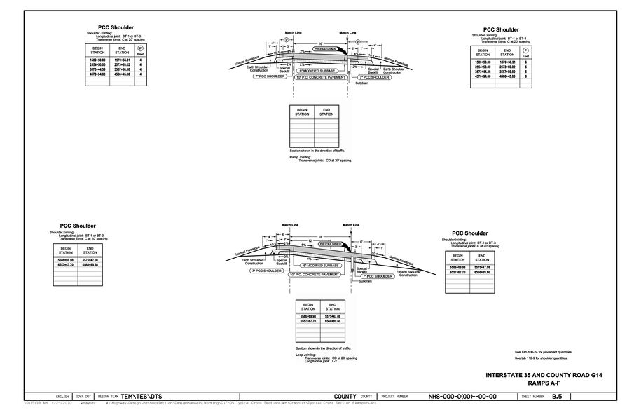
Ramp typical cross sections for an interchange should be shown on a single sheet or on consecutive sheets. The designer should not combine ramp typical cross section for multiple interchanges on a single sheet, even if the dimensions are the same.
Interchanges which have more than one type of ramp should be shown on one sheet or on consecutive sheets.
View a sample below.
\({\Large Attention:}\)
NOTE: Ramp typicals are shown in the direction of traffic. The designer should not mirror the typical to display in the direction of stationing.
Back to top
Granular Roadways
Typical sections for granular roadways are to be shown on Typical 2_GradeGran.
Back to top